Use the manual’s settings and measurement method, confirm free steering travel, then change one alignment variable at a time.
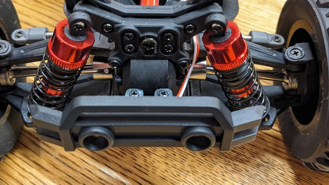
Publisher-review chassis photograph of the MJX Hyper Go 14210, useful for visual inspection context only; it is not a Torquehouse teardown or condition assessment.
QuadifyRC (review image; photographer not individually credited) · Copyrighted publisher-review imagery; permission pending
Photo credit & source ↗View the teaching schematic
Goal
Keep the drive battery disconnected. Place the vehicle on a level setup surface in the ready-to-run loading condition specified by its manual, with the intended wheels, tires and battery mass present. Camber describes wheel lean viewed from the front or rear; toe describes the direction the wheels point viewed from above. Both are geometry observations, not shortcut diagnoses. A bent arm, damaged hub, worn ball end, loose servo saver or tire problem can make a measured angle misleading.
Inspect before alignment
Start with the exact vehicle manual or setup sheet. The Team Associated Apex manual has a dedicated camber/toe section with model-specific starting values and a camber-gauge reference. These are examples of the detail to seek in your own manual, not values to copy. That context is important: do not import a setting from another platform, scale or tire class and treat it as a safe default.
Establish the manual baseline
Inspect first. With power disconnected, turn the steering from lock to lock and check that links do not bind, tires do not rub, and left/right steering movement is plausible. Examine turnbuckles, rod ends and mounting points for cracks, missing retainers or play. If a wheel cannot hold a repeatable position because a part is damaged, stop; an alignment setting will not cure it.
Set the steering trim and mechanical center according to the radio and vehicle manual before measuring toe. Powered centring is a separate controlled step; disconnect power before adjusting links, and never force a connected servo through its travel. Use a setup gauge if the manual calls for it, or the manufacturer’s specified reference method. For camber, use the same setup surface and tire condition on both sides. Make small, documented, matched adjustments where the manual permits; do not twist a turnbuckle until the car “looks right.”
Hypothetical example: after a front-arm replacement, the left front has visibly different lean from the right. First verify the correct arm, hub and link location, then restore the manual baseline and record it. Only after a controlled run should you decide whether a single documented adjustment is warranted. A useful record includes front/rear, left/right, reference method, surface, tires and reason for the change. Stop for binding, damaged threads, a servo that cannot center, tire rub, or an angle that cannot reach the manual baseline without forcing a part. The baseline is successful when it is repeatable and the car’s mechanical condition is known.
After an impact
After a crash or replacement, compare side-to-side hardware before chasing an angle. Record turnbuckle turns only as a return path to your own baseline, not a portable value. Recheck steering travel unpowered after each adjustment. The final note should state what was measured, how, and why; it should not claim the geometry is universally optimal.
Small decision table
| Observation | First check | Do not assume |
|---|---|---|
| Car pulls | Tire and steering freedom | A toe value fixes damage |
| One wheel leans differently | Correct part and link location | More turnbuckle force helps |
| Steering rubs | Travel and wheel clearance | Alignment alone is the cause |
Leave with a useful record.
This is a reading aid, not a safety certification. Checks stay only on this page and reset when you reload.
Sources & scope
Primary references checked September 19, 2026. These dates describe source review, not publication of this site. Examples labelled hypothetical or illustrative are not tests.
Team Associated — Team Associated Apex Manual
Supports: camber and toe are manufacturer-documented setup settings.
Limit: Camber/toe section verified through indexed manufacturer PDF text on 2026-09-19; full PDF retrieval exceeded the reader size limit. Model-specific target angles are not generalized.
Source publication: not established · Checked: 2026-09-19