An exploded view identifies relationships; it does not replace the model-specific assembly sequence.
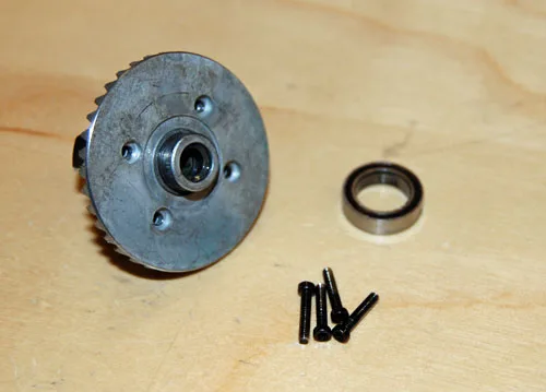
Manufacturer workshop image: ring-gear assembly being removed from the Axial differential housing.
This is an Axial differential ring-gear assembly, not a spur-gear or universal bearing procedure.
Axial Adventure; Bender's AX10 Ridgecrest Stage 3 (photographer not identified) · Manufacturer copyright; permission required before public release
Photo credit & source ↗View the teaching schematic
An exploded view is a relationship map. It shows which pieces belong together and how an assembly is oriented, but a callout number does not automatically state the removal order. Start with the exact model and revision; a diagram for a similar chassis can be close enough to confuse and different enough to cause a mistake.
Anchor the page
Find the drawing’s front, rear, left and right, then place the unpowered car on the bench in the same orientation. Locate the assembly you need—front hub, gearbox, steering rack or shock tower—and trace it inward toward the chassis. On a manual such as Tamiya’s TT-02 instructions, hardware codes, part shapes and staged drawings work together; the useful evidence is the relationship shown on that page, not a generic assumption about RC construction. See the Tamiya TT-02 manual.
Translate symbols into a service note
Before removing anything, write a proposed chain from the outside inward. For a hypothetical front-bearing job it might read “wheel hardware → hex and pin → axle/carrier relationship → bearing,” but keep only steps confirmed by the exact instructions. Beside each step, note the part callout, hardware label and orientation cue. The diagram can identify where a bearing sits; it cannot supply an unstated tool, lubricant or torque.
Preserve spatial information
Photograph every layer before lifting it. Place removed parts on a clean tray in the drawing’s orientation and bag hardware by assembly or manual step. Keep left and right groups separate even when parts look symmetrical. For wiring, photograph the route and plug orientation before releasing clips. Never move gears, shafts or steering parts under power.
Use a three-way reassembly check
At each stage compare the drawing, the pre-removal photograph and the physical fit. A part should seat in the depicted orientation without a guessed workaround. Before closing a cover, account for every removed fastener and any shim, pin or spacer. Then check the relevant movement gently by hand with the drive battery disconnected.
Use the completed note as a future service map. Add the date, symptom and reason the assembly was opened, but do not rewrite the manufacturer’s sequence as though your note were an official instruction. Record any installed option part separately from the stock callout. On the next service, verify that the manual revision and installed parts are still the same before relying on it.
If a fastener does not start normally, a left/right part will not seat, the wire route conflicts with the drawing or the manual revision differs from the vehicle, stop. Mark the unresolved callout and send the model number, page and photographs to official support or a qualified shop. That is more actionable than reporting that the diagram “looks wrong,” and it preserves a recovery path without forcing the assembly.
Leave with a useful record.
This is a reading aid, not a safety certification. Checks stay only on this page and reset when you reload.
Sources & scope
Primary references checked September 19, 2026. These dates describe source review, not publication of this site. Examples labelled hypothetical or illustrative are not tests.
Tamiya — TT-02 Chassis Instruction Manual
Supports: Manufacturer assembly diagram and model-specific component relationship context..
Limit: The articles are editorial workflows; exact tools, order and parts remain the readers own model manual.
Source publication: not established · Checked: 2026-09-19