Photo credit & source ↗
BENCH GUIDE 3 MIN READ
Steering works, but there is no drive: narrow the fault safely
A symptom-led check that avoids turning one no-drive problem into two.
Open the guide ↗LEARN / POWER SYSTEMS
Motor construction, ESC mode, voltage, gearing, tyre load, cooling and terrain all interact. This page makes a few relationships visible; it does not prescribe a universal setup or predict a vehicle’s output.
01 / CONSTRUCTION
Compare the switching location, then step through the sequence. Texas Instruments: mechanical versus electronic commutation ↗
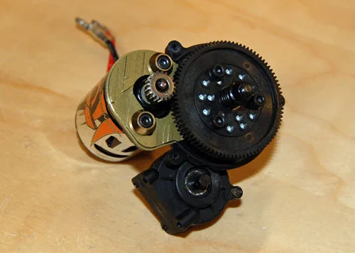
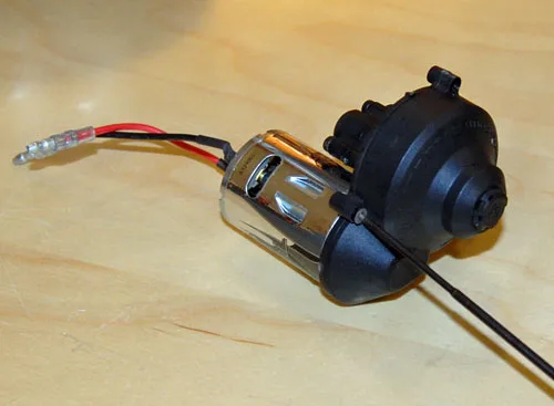
Brushes make electrical contact with a commutator on the rotating armature; the commutator changes the armature connection as it turns. A current Tamiya 33T 540 listing is one example of a brushed, low-RPM/high-torque motor intended for R/C truck use.
The rotor carries magnets while the ESC switches stationary stator windings. The construction diagram is intentionally simplified: it explains the switching location, not a detailed magnetic-field model. Castle’s current sensored-motor listing identifies a stacked stator and rotor in one surface-motor example.
Static schematic. Motion is illustrative, not RPM-scale.
02 / FEEDBACK
A sensor cable can provide rotor-position information to a compatible ESC at startup and low speed. It can support more deliberate low-speed behavior in a compatible system; it does not guarantee a particular crawl result.
A sensorless ESC estimates rotor position from motor behavior. It can be appropriate across many applications, but startup feel and low-speed control depend on the complete system and tune. Some ESCs support both modes with stated limits.
Hobbywing’s current surface catalogue distinguishes sensored and sensorless products, while its MAX10 G2S listing identifies a sensored ESC and supported motor/vehicle ranges. Catalogue · MAX10 G2S
03 / INTENT
Crawl priority: aim for repeatable low-speed control and watch temperatures; this is not a universal component recommendation.
Kv: no-load RPM per volt, not a power or torque rating. Turns: a winding label whose meaning is not reliable for cross-model comparison without the manufacturer’s data. Compare the exact motor’s specifications and compatibility notes instead.
04 / TWO-SPEED LEVER
Low gear selected: greater ideal reduction, lower ideal output RPM.
Assumptions: fixed motor RPM, no slip and an ideal reduction. Output RPM = motor RPM ÷ reduction. The displayed multiplier only expresses ideal ratio leverage; it is not a guaranteed wheel-torque product. Battery sag, ESC and motor limits, tyres, losses, terrain and transmission design change real results.
A symptom-led check that avoids turning one no-drive problem into two.
Open the guide ↗A careful mesh check that begins with the correct gear and ends with a temperature-aware run.
Open the guide ↗A faster lap is a clue, not a verdict. Compare repeatable runs, record mistakes and return to the baseline before drawing a conclusion.
Open the guide ↗